4DoF Motion Flight Simulator
This project integrates an Arduino microcontroller, two sepereate 2-axis joystick, and multiple continuous servos to translate analog inputs into real-time physical flight movements via a 4-string suspension rig. The primary challenge was severe voltage sag and random motor spinning caused by drawing too much current from the Arduino’s 5V pin, which repeatedly crashed the USB port connection. I learned that wire magament is essential to the suceess of ones own project as it makes way for ease of debugging. I also leanred that while some things may work or seem perfect on paper, they can actually be screwed up during real physical tests, no mater how prepared you are.
| Engineer | School | Area of Interest | Grade |
|---|---|---|---|
| Smayan Beedanagari | Dougherty Valley High School | Aerospace Engineering | Incoming Sophmore |
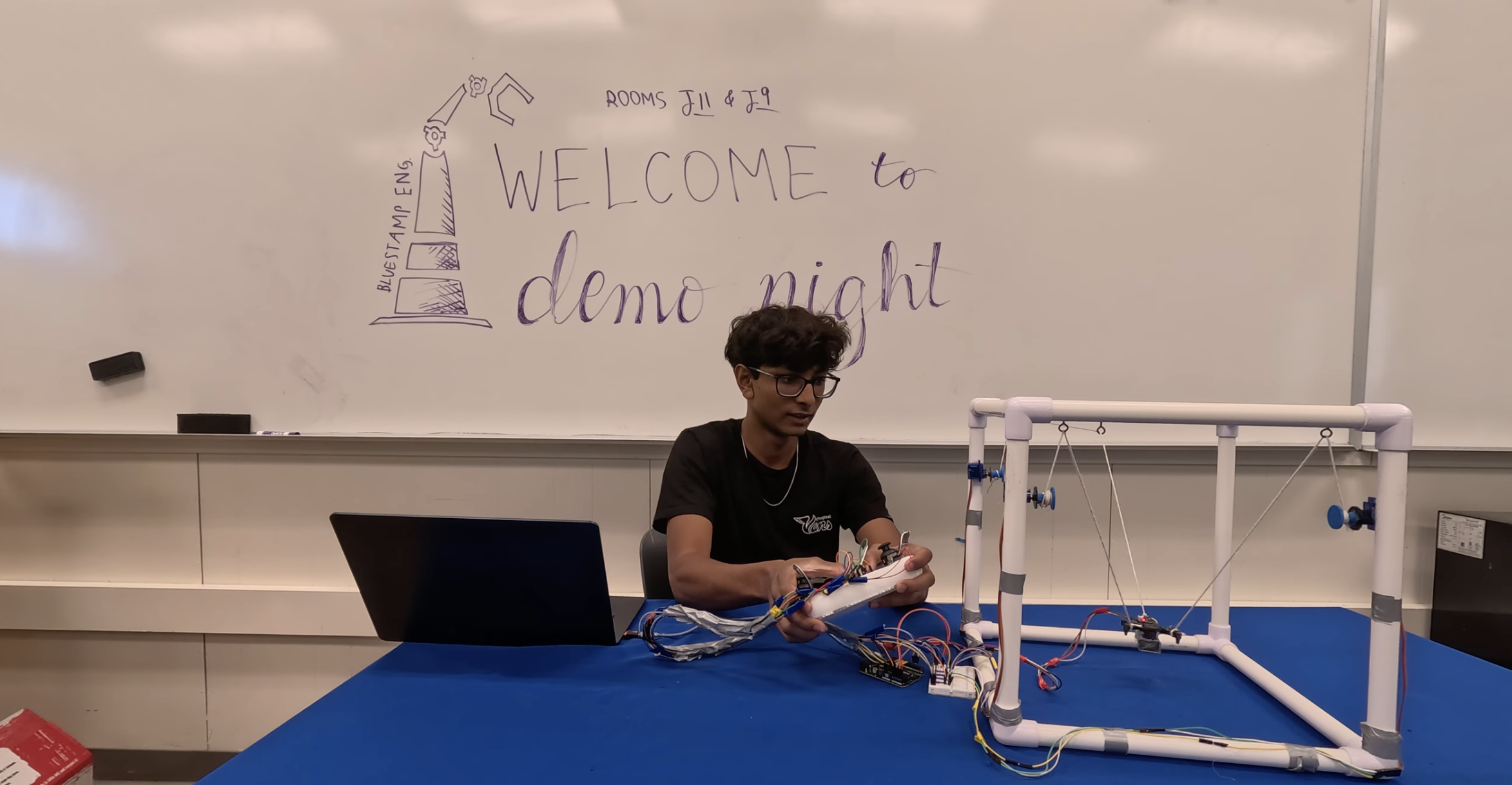
Third Milestone
Project Overview
This final phase focuses on the gyroscope that trakcs he x, y, and. coordinates within the system as well as calculate the pitch, yaw and rotation, and then displaying that information on the arduino uno serial monitor. This allows for the user to debug and track exactly where the spacecraft is located within the box
Technical Progress
The 3-string suspension rig now includes the gyroscope and also includes the very precise position of where the spacecraft is located at. I fine tuned the coordinte tracjing simulation to figure out within a few millimeters of where the spacecraft is located at.
Takeaways
The biggest takeaway I had from Bluestamp was learning exactly how a engineer is able to complete their project while also tracking their project with detail. Another big thing i leaned from BSE is how a engineer is able to use the engineering process to debug and finish a project.
Next Steps
-Bluetooth Module: Use a bluetooth module instead of the wiring sstem i have currently which would allow for me to connect from anywhere in the clasroom
Second Milestone
Project Overview
This phase focuses on the complete physical assembly and wiring of the controller. It includes 6 buttons and 2 joysticks which help maneuver the spacecraftar ound the box. Joysticks are used for basic x, y, and z movement, and he buttons allow fr pitches up, down, and yaw left and right giving access to 6 DOF, however in real world application due to the servos and arduinos limited processing power yaw is not achievable and pitch is very limited with 3 motors
Technical Progress
The 3-string suspension rig is fully assembled, and the cockpit chassis is successfully suspended within the PVC frame. The control system has been upgraded to include the second joystick and motor control buttons. Lines are routed from the continuous servos to the central rig, and the software flight mixer now calculates outputs for combined 3D motion and elevation control.
Challenges & Solutions
-Line Sag & Calibration: Uneven weight distribution on the PVC frame can cause unwanted twisting, which I’ll fix by adding physical counterweights.
Next Steps
-System Testing: Fine-tune the PVC counterweights to ensure the cockpit centers automatically when joysticks are released.
-Final Mechanical Calibration: Assemble the 3-string suspension rig and hang the cockpit chassis to complete the project
First Milestone
Project Overview
This project is a physical flight simulator chassis built from PVC pipes and a 4-string suspension rig. It integrates an Arduino, a joystick, and four continuous-rotation servos to simulate physical flight motion. Moving the joystick sends X and Y signals to the Arduino, which calculates and spins the servos to physically tilt or pull the suspended cockpit forward, backward, left, or right.
Technical Progress
The core electronics and basic flight logic are fully operational. The four servos are securely mounted to the PVC frame, and a single joystick is wired and functioning. The software successfully processes the vector mixing, meaning a joystick input accurately commands the specific combination of servos needed to move the rig.
Challenges & Solutions
-Mechanical Tension: Continuous servos pulling strings will definitively slack or erratic shaking during sudden joystick inputs.
-Software Smoothing: I’m solving this by widening the deadzones and smoothing out the motor acceleration profiles in the code.
-Chassis Balance: Uneven weight distribution on the PVC frame can cause unwanted twisting, which I will fix by adding physical counterweights.
Next Steps
-Milestone 2: Attach the lines to the servos and calibrate structural movements to match the joystick inputs, and add in the second joystick and altitude buttons for full Z-axis
-Milestone 3: Assemble the 4-string suspension rig and hang the cockpit chassis to complete the project
Starter Milestone
Project Overview
I designed and built a handheld retro arcade console from scratch. The hardware features an 8x16 LED matrix screen for visuals, a 3-digit display for real-time score tracking, and a 7-button layout for the controls. On the software side, the console runs five different playable games and includes an automated save system that keeps track of high scores even after the device is turned off.
Technical Progress
The console is fully assembled, soldered, and 100% operational. During testing, everything booted up smoothly—the games load without errors, the buttons feel responsive with zero noticeable lag, and the high-score memory system tracks and saves data exactly as planned.
Challenges & Solutions
The biggest hurdle was definitely the soldering. Dealing with so many dense, closely packed connections on a compact board was incredibly frustrating at first. My early attempts were messy and risked shorting out the components. To fix this, I took a step back, practiced my wire management, and learned how to better regulate the iron’s heat. With some patience, my technique drastically improved, and I was able to finish the rest of the board with clean, solid joints.
Future Plan: Flight Simulator Chassis
Now that the arcade console is complete, I’m moving on to my intensive project: building a physical flight simulator chassis.
Next Steps
-The Frame: Assembling a rigid, lightweight cockpit structure out of PVC pipes.
-The Rigging: Setting up a custom 4-string rig to handle motion physics.
-Controls & Automation: Figuring out wether buttons, potentiometers, or even joysticks are the way to go in terms of controls, and when selected integrating that control into the breadboard
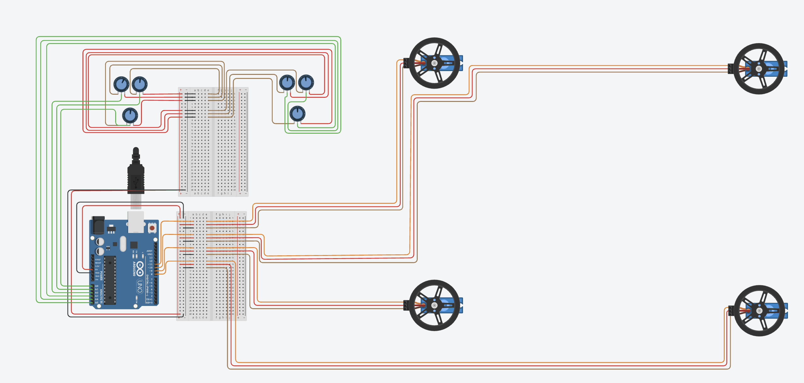
Schematic
Code
This Arduino program runs a 3-motor flight simulator rig by mixing joystick and button inputs. It filters out hardware jitters using custom deadzones, combines your movements (pitch, roll, yaw, and lift) mathematically, and outputs the final speeds to four continuous servos.
System Initialization and Pin Mapping
This section maps your physical hardware connections to specific Arduino pins and initializes the system. On startup, it sets all four motors to a universal “stop” position (90) so the simulator chassis doesn’t violently jump when powered on.
#include <Servo.h>
#include <Wire.h>

Servo servo3;
Servo servo4;
Servo servo5;

const int pin3 = 3;
const int pin4 = 4;
const int pin5 = 5;

const int PIN_VRX = A0;      // Joystick 1 Up / Down
const int PIN_VRY = A1;      // Joystick 1 Left / Right vector slide

// Button Mapping
const int PIN_BTN8  = 8;     // Motor 4 Clockwise
const int PIN_BTN9  = 9;     // Motor 4 Counter-Clockwise
const int PIN_BTN10 = 10;    // Motor 5 Clockwise
const int PIN_BTN11 = 11;    // Motor 5 Counter-Clockwise
const int PIN_BTN12 = 12;    // Motor 3 Clockwise
const int PIN_BTN13 = 13;    // Motor 3 Counter-Clockwise

const int STOP_VAL = 90;
const int DEADZONE = 120;
const int SPEED_VAL = 140;

// MPU6050 I2C Address
const int MPU_addr = 0x68;
int16_t AcX, AcY, AcZ, Tmp, GyX, GyY, GyZ;

// Calibration offsets
int offsetX = 0;
int offsetY = 0;
int offsetZ = 0;

// Filtered / smoothed telemetry variables to stop jitter
float smoothX = 0;
float smoothY = 0;
float smoothZ = 0;
Setup Function void(setup)
The setup runs once when the microcontroller turns on. It initializes communication, configures pin modes, attaches servos, and calibrates the MPU6050 sensor.
void setup() {
  Serial.begin(9600);
  delay(1000);

  Serial.print("hello it is working");

  // Initialize I2C and wake up the MPU6050
  Wire.begin();
  Wire.beginTransmission(MPU_addr);
  Wire.write(0x6B);  // PWR_MGMT_1 register
  Wire.write(0);     // Wake up MPU-6050
  Wire.endTransmission(true);

  // Configure digital button pins using internal pull-up resistors
  pinMode(PIN_BTN8, INPUT_PULLUP);
  pinMode(PIN_BTN9, INPUT_PULLUP);
  pinMode(PIN_BTN10, INPUT_PULLUP);
  pinMode(PIN_BTN11, INPUT_PULLUP);
  pinMode(PIN_BTN12, INPUT_PULLUP);
  pinMode(PIN_BTN13, INPUT_PULLUP);

  // Attach servos and command them to stay stationary at startup
  servo3.attach(pin3);
  servo4.attach(pin4);
  servo5.attach(pin5);

  servo3.write(STOP_VAL);
  servo4.write(STOP_VAL);
  servo5.write(STOP_VAL);

  // Quick calibration read on startup (keep it flat!)
  delay(500);
  long sumX = 0, sumY = 0, sumZ = 0;
  for (int i = 0; i < 50; i++) {
    Wire.beginTransmission(MPU_addr);
    Wire.write(0x3B);
    Wire.endTransmission(false);
    Wire.requestFrom(MPU_addr, 6, true);
    sumX += (int16_t)(Wire.read() << 8 | Wire.read());
    sumY += (int16_t)(Wire.read() << 8 | Wire.read());
    sumZ += (int16_t)(Wire.read() << 8 | Wire.read());
    delay(10);
  }
  offsetX = sumX / 50;
  offsetY = sumY / 50;
  offsetZ = (sumZ / 50) - 16384;

  Serial.println("System Initialized: Compact Single-Line Active");
}
Sensor Data Reading & Processing
This part continuously reads raw acceleration data, removes calibrated offsets, maps it to a workable range, and applies a smoothing filter.
void loop() {
  // --- 1. READ MPU6050 GYRO/ACCEL VALUES ---
  Wire.beginTransmission(MPU_addr);
  Wire.write(0x3B);
  Wire.endTransmission(false);
  Wire.requestFrom(MPU_addr, 6, true);

  AcX = Wire.read() << 8 | Wire.read();
  AcY = Wire.read() << 8 | Wire.read();
  AcZ = Wire.read() << 8 | Wire.read();

  // Subtract startup offsets
  int calX = AcX - offsetX;
  int calY = AcY - offsetY;
  int calZ = AcZ - offsetZ;

  // Map values (-500 to +500)
  int rawX = constrain(map(calX, -16384, 16384, -500, 500), -500, 500);
  int rawY = constrain(map(calY, -16384, 16384, -500, 500), -500, 500);
  int rawZ = constrain(map(calZ - 16384, -16384, 16384, -500, 500), -500, 500);

  // Apply Exponential Smoothing
  float alpha = 0.2;
  smoothX = (alpha * rawX) + ((1.0 - alpha) * smoothX);
  smoothY = (alpha * rawY) + ((1.0 - alpha) * smoothY);
  smoothZ = (alpha * rawZ) + ((1.0 - alpha) * smoothZ);

  // Shift values up by adding 5000 to the current total
  int shiftedX = (int)smoothX + 5000;
  int shiftedY = (int)smoothY + 5000;
  int shiftedZ = (int)smoothZ + 5000;
Section 4: Input Reading (Buttons & Joystick)
This section reads the states of all manual input controls.
// --- 2. READ BUTTONS & JOYSTICK ---
  bool btn8  = (digitalRead(PIN_BTN8) == LOW);
  bool btn9  = (digitalRead(PIN_BTN9) == LOW);
  bool btn10 = (digitalRead(PIN_BTN10) == LOW);
  bool btn11 = (digitalRead(PIN_BTN11) == LOW);
  bool btn12 = (digitalRead(PIN_BTN12) == LOW);
  bool btn13 = (digitalRead(PIN_BTN13) == LOW);

  int vrx  = (analogRead(PIN_VRX) - 512) * -1;
  int vry  = (analogRead(PIN_VRY) - 512);

  int m3 = STOP_VAL;
  int m4 = STOP_VAL;
  int m5 = STOP_VAL;
Section 5: Control & Motor Logic
This section resolves inputs to decide motor speeds and directions. Buttons take priority over joystick inputs.
// --- 3. MOTOR LOGIC ---
  // Button controls (Individual motor manual overrides)
  if (btn8 && !btn9) {
    m4 = SPEED_VAL;
  }
  else if (btn9 && !btn8) {
    m4 = 180 - SPEED_VAL;
  }

  if (btn10 && !btn11) {
    m5 = SPEED_VAL;
  }
  else if (btn11 && !btn10) {
    m5 = 180 - SPEED_VAL;
  }

  if (btn12 && !btn13) {
    m3 = SPEED_VAL;
  }
  else if (btn13 && !btn12) {
    m3 = 180 - SPEED_VAL;
  }

  bool anyButtonPressed = (btn8 || btn9 || btn10 || btn11 || btn12 || btn13);

  // Joystick control (Vector movement when no buttons are held)
  if (!anyButtonPressed) {
    if (vrx < -DEADZONE) {
      m3 = SPEED_VAL;
      m4 = 180 - SPEED_VAL;
      m5 = SPEED_VAL;
    }
    else if (vrx > DEADZONE) {
      m3 = 180 - SPEED_VAL;
      m4 = SPEED_VAL;
      m5 = 180 - SPEED_VAL;
    }
    else if (abs(vry) > DEADZONE) {
      if (vry < -DEADZONE) {
        m4 = SPEED_VAL;
        m5 = 180 - SPEED_VAL;
        m3 = SPEED_VAL;
      } else {
        m4 = 180 - SPEED_VAL;
        m5 = SPEED_VAL;
        m3 = 180 - SPEED_VAL;
      }
    }
  }

  // Write finalized calculated values to hardware physical servos
  servo3.write(m3);
  servo4.write(m4);
  servo5.write(m5);
Section 6: Telemetry Output & Loop Delay
Formats system data into a clean, single-line telemetry string and outputs it to the Serial Monitor.
// --- 4. CONTINUOUS TIGHT STREAM WITHOUT EXTRA SPACING LINES ---
  char buffer[64];

  // Fixed-width formatting with 5-digit slots to prevent text layout shifting side-to-side
  sprintf(buffer, "X:%5d Y:%5d Z:%5d  ||  M3:%3d M4:%3d M5:%3d",
          shiftedX, shiftedY, shiftedZ, m3, m4, m5);

  Serial.println(buffer);

  delay(10);
}
Bill of Materials
| Part | Note | Price | Link |
|---|---|---|---|
| Arduino Uno R3 | Motherboard of the Flight Sim | $49 | Link |
| Continuous Rotation Servos | Pulls or Loosens String on Flight Sim | $16 | Link |
| Joystick Modules | Used to Control Servos | $13 | Link |
| Button Modules | Used to Control Servos | $9 | Link |
| Metal Screw Eyes | Used to Route String to Spacecraft | $7 | Link |
| Slick String | Attaches from Servo to Spacecraft | $7 | Link |